Column Loading Basics
Screws which are loaded in compression may be so slender (long in relation to diameter) that they can fail by elastic instability (buckling) much before they reach their static load limit or compressive strength. A screw system design which undergoes a compressive load must be checked for safe column loading.
Basic safe column loads are shown in graphic form in (Figure 30). Using the minor diameter of the screw from the Screw/Nut Engineering Data section for the selected screw and the unsupported length of the screw, find the basic maximum column load from the graph.
Calculate the safe column load using this formula. If your actual load exceeds the calculated safe load, then increase the screw diameter or change the end fixity. Repeat the process until the calculated safe load is greater than your expected loads.
Column Loading Example
A 1 – 5 Acme screw is selected to support a load of 7,000 lbs. with an unsupported span of 30 in. The screw will have one end fixed and one end supported and a factor of safety of 1.75 will be used.
- Using the screw minor diameter for a 1 – 5 Acme screw of .750 in. (from the Acme Screws/Nuts – Engineering Data page) and a length of 30 in., the maximum column load of approximately 5,000 lbs. can be read from this graph.
- The safe column load is 5,714 lbs. (5,000 lbs. x 2.0/1.75) where 2.0 is the correction factor for one end fixed and one end supported and 1.75 is the factor of safety.
- Since the intended load of 7,000 lbs. exceeds the safe column load of 5,714 lbs., a larger screw should be selected.
- Using the same desired conditions as above, a 1 1/4 – 5 Acme screw will have a safe column of 18,286 lbs.
- From the graph at 1.00 minor diameter and 30 in., the basic maximum column load of approximately 16,000 lbs. is read.
- The safe column load is 18,286 lbs. (16,000 x 2.0/1.75) where 2.0 is the correction factor for one end fixed and one end supported and 1.75 is the factor of safety.
- The safe column load of 18,286 lbs. exceeds the desired load of 7,000 lbs. and the 1 1/4 – 5 size screw should be selected.
- Note how dramatically the safe column load increases. For a 25% increase in screw major diameter, the safe column load increased from 5,714 lbs. to 18,286 lbs. (An increase of 220%!)
All the data presented in Figure 30 are for ideal, pure axial loading, with supported-supported end fixity. Off center loading and moment loading will require additional derating of the basic column load. A screw lift system properly designed for pure axial loading may readily fail when eccentric loading produces additional bending in the screw.
For data points beyond the range of the graphs, contact Roton Application Engineering.
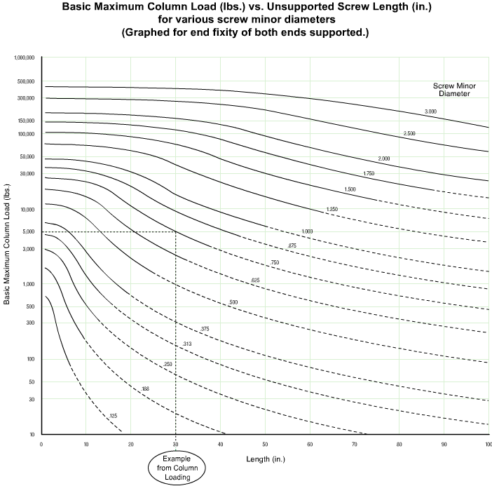
FIGURE 30